Schematic Soil Moisture Sensor Arduino Circuit Diagram

Simple Soil Moisture Detector Circuit Circuit Diagram Circuit Electronics Circuit

Arduino Soil Moisture Sensor And Code Arduino Projects Arduino Simple Arduino Projects

Arduino Based Irrigation And Automatic Plant Watering System Using Soil Moisture Sensor Build Automatic Wate Plant Watering System Aquaponics System Aquaponics

Pin On Arduino Project

Soil Moisture Sensor With Arduino Schematic Diagram Random Nerd Tutorials Arduino Sensor Moisturizer

Green House Monitoring Using Arduino Soil Moisture Sensor Circuit Diagram Arduino Humidity Sensor Circuit Diagram
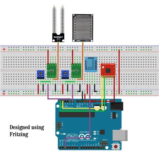
The sensor module contains a potentiometer with it which is used to set the threshold value.
Schematic soil moisture sensor arduino circuit diagram. Digital mode interfacing arduino and soil moisture sensor. The soil moisture is monitored in real time. This is very simple and interesting circuit for electronics lovers. Don t change the supply voltage or the 220k as these two values are correct for this circuit.
In the schematic from left we have our soil moisture sensor which is connected to a driver board preety much any soil moisture sensor comes with a driver board example soil moisture meter soil humidity sensor. The circuit diagram for this is very simple. A 12volt dc water pump is controlled as the soil moisture increases or decreases below a certain pre defined value. In this project we are going to build a transistor based simple soil moisture detector circuit.
Soil moisture sensor works on the principle of open and closed circuit. 1 to proceed with its. The soil moisture sensor module built around the lm393 comparator gives an active low l level output when the soil is dry determined by a pre setted threshold value. The circuit can be used to detect moisture in any substance like plants soil wood wall floor irrigation areas etc.
To connect the soil moisture sensor fc 28 in the digital mode we will connect the digital output of the sensor to the digital pin of the arduino. When soil is moist the current will start flowing from one terminal to another working as a closed circuit. Connect the vcc pin to 3 3v of arduino and gnd to gnd. Now lets interface the capacitive soil moisture sensor with oled display arduino and display the analog value or soil moisture value in percentage.
This soil moisture sensor circuit can be used in many applications like automatic plant irrigation system greenhouse projects etc. We have interfaced the moisture sensor with arduino uno board. Circuit diagram of the digital soil moisture meter front end of the digital soil moisture meter is a simple soil moisture sensor head built around a few easily available parts. Working of the sensor head electronics is self explanatory so just follow the conceptual drawing and schematic drawing shown in fig.
This digital output wet soil l dry soil h is routed to one i o terminal d2 of the arduino microcontroller. Under the circuit diagram section we have our schematic made with fritzing also underneath that we have the practical test setup. In the previous circuits of moisture sensors like plant soil moisture tester circuit or moisture sensor alarm. Based on this input at d2 arduino gives an active.
I have given below soil moisture sensor circuit diagram. When the soil is dried no current will flow through it and it works like an open circuit. Capacitive soil moisture sensor arduino in this tutorial you will learn how to use the capacitive soil moisture sensor v1 2 with arduino and display the soil moisture value on a 16 2 i2c lcd module.

Iot Based Smart Irrigation System Using Soil Moisture Sensor And Esp8266 Nodemcu Iot Projects Irrigation System Arduino Projects

A Very Simple Mud Or Soil Moisture Tester Circuit Can Be Built By Using A Single Opamp And A Few Passive C Circuit Projects Electronic Circuit Projects Circuit

Arduino Controlling Relay Moisture Sensor Fritzing Project Soil Moisture Sensor Test Arduino Sensor Moisturizer

Auto Irrigation System Using Soil Moisture Sensor And Pic Microcontroller Irrigation System Irrigation Pic Microcontroller

Soil Moisture Sensor With Arduino Tutorial45 Arduino Arduino Projects Electronics Projects For Beginners

Arduino Irrigation And Automatic Plant Watering With Soil Moisture Sensor Manufacturingstories Arduino Arduino Sensors Arduino Projects

Arduino Based Automatic Plant Irrigation System With Message Alert Arduino Arduino Projects Arduino Laser

Arduino Soil Moisture Sensor Relay Control Arduino Arduino Radio Sensor

Pin On Electronics

Pin On Arduino

Build Your Own Diy Automatic Irrigation System Using Arduino Soil Moisture Sensor And A Solenoid Valve Automatic Irrigation System Arduino Radio Irrigation

Smart Irrigation System Circuit Diagram And Code Irrigation System Circuit Diagram Electronic Schematics

Soil Moisture Detector Circuit Diagram Electronics Circuit Detector Circuit Diagram

Watering System Introduction Arduino Projects Water Systems Arduino

Temphummoistureiotv2 Iot Sensor Humidity Sensor

Dht11 Humidity And Temperature Sensor On Arduino With Lcd Arduino Lcd Arduino Circuit Arduino

A Cheap Soil Moisture Sensor Gardenbot Irrigazione

Arduino Whistle Detector Switch Using Sound Sensor Arduino Arduino Projects Sensor
3

Arduino Distance Detector With A Buzzer And Led S Arduino Arduino Projects Buzzer Arduino

Pin On Sensing And Sensors And Some Actuation

A Panosundaki Pin

Arduino Soil Moisture Sensor With Images Arduino Sensor Moisturizer
Diy Arduino Weather Station Aws Weather Station Arduino Arduino Projects

Simple Automatic Plant Watering Circuit Homemade Circuit Projects Electronic Circuit Projects Electrical Engineering Projects Irrigation Diy

Circuit To Read Data From A Water Flow Sensor Using Arduino Read More At Http Www Haberocean Com 2015 05 Circuit T Arduino Arduino Circuit Sensor

Simple Water Level Indicator Electronic Schematics Circuit Diagram Electronic Engineering

Arduino Soil Moisture Sensor Arduino Sensors Arduino Arduino Projects

Soil Moisture Sensor Module Circuit In 2020 Sensor Ldr Sensor Microcontrollers

Iot Based Smart Irrigation System Using Soil Moisture Sensor And Esp8266 Nodemcu Irrigation System Iot Iot Projects

Watering System Introduction Water Systems Electronic Circuit Projects Automatic Watering System

Pin On Smart Home Automation

Build Arduino Based Home Security System Using Pir Motion Sensor Home Security Best Home Security Best Home Security System

Garduino Geek Gardening With Arduino Make Arduino Electronic Schematics Aquaponics

Automatic Plant Watering System Plant Watering System Arduino Arduino Board

Arduino Lcd Soil Moisture Sensor Arduino Lcd Arduino Moisturizer

Soil Moisture Sensor Module Pinout In 2020 Sensor Moisturizer Ldr Sensor

Pin On Arduino Projects


Arduino Based Automatic Plant Irrigation System With Message Alert Irrigation System Irrigation Diy Irrigation

Arduino Soil Moisture Sensor Relay Control In 2020 Arduino Arduino Programming Sensor

A4988 Arduino Stepper Motor Wiring Schematic Diagram Pinout In 2020 Stepper Motor Stepper Motor Arduino Arduino

